How to Calculate a Distribution Board Load, Step by Step
- Ziad Eltaky
- 3 min read
- October 23, 2026
Calculating the load of a distribution board is the first step in any electrical design. The main breaker, the cable and the transformer are all chosen from it. A mistake means either an overloaded board that heats up and trips, or an oversized one that costs more for nothing. Here is the method I follow in the office and on site.
Step 1: List the loads
Write each load on its own line: description, power in watts or kilowatts, quantity and type (lighting, sockets, air conditioning, motors, heaters). Do not rely on the architectural drawings alone. Check air conditioner and pump ratings with the mechanical designer, because they are usually the largest part.
Step 2: Connected load
The connected load is the sum of all device ratings as if everything ran at once. You do not size the breaker on this number, but it is the starting point.
Step 3: Demand factor and diversity
The demand factor is the share of the connected load that actually runs (not every socket draws full power at the same moment). The diversity factor reflects that peaks on different boards do not happen together. Values depend on the adopted code and building type, so use the tables in your local code and never copy numbers from another project.
Demand load = connected load × demand factor.
Step 4: Current
- Three-phase:
I = P ÷ (√3 × V × PF)where V is the line-to-line voltage. - Single-phase:
I = P ÷ (V × PF).
Example: demand load 45 kW, 400 V, power factor 0.85:
I = 45000 ÷ (1.732 × 400 × 0.85) ≈ 76.4 A
Step 5: Choose the breaker
For continuous loads many codes require the breaker rating to exceed the load current by 25%. In the example: 76.4 × 1.25 ≈ 95.5 A, so the next standard size up is 100 A. The cable must then suit this breaker, which is covered in the cable sizing and voltage drop guide.
Step 6: Balance the phases
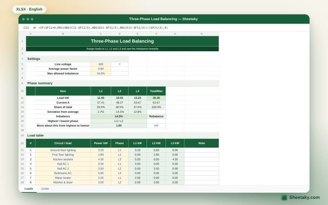
Spread single-phase circuits across the three phases so the current in each is close. A large imbalance overloads one phase, heats the neutral and wastes board capacity. The load balancing sheet shows the difference between phases instantly.
Step 7: Spare capacity
Leave room for future expansion. Most designers keep 20% to 25% spare capacity and empty breaker ways.
Common mistakes
- Adding apparent power (kVA) and real power (kW) in the same column.
- Ignoring motor starting current when selecting protection.
- Forgetting the power factor, which makes the amps look lower than they are.
- Using a demand factor from a table for a different building type.
Try it yourself
The next sheet combines all the steps in one table: the electrical load calculator. Enter the loads and demand factors and it returns the load and current. Values in this guide are illustrative for learning, so always check the code you work under.
Download the related sheets

Electrical engineering
Electrical Load Calculator in Excel: Current and Transformer Size
A ready Excel sheet to calculate electrical loads with demand factor and power factor, returning current, kVA and…
Electrical engineering
Three-Phase Load Balancing Sheet in Excel with Imbalance Percentage
An Excel sheet to spread panel loads across L1, L2 and L3. It calculates load and current per…

Electrical engineering
Cable Voltage Drop Calculator in Excel for Multiple Circuits
An Excel sheet that checks voltage drop in several circuits at once from current, length and mV/A/m, compared…
Get every new sheet and guide
A short, useful email when a new sheet or guide is added. Unsubscribe any time.